Category Archives: VFD

VFD’s and Long Motor Leads

Recently I came across an application where multiple motors were failing at a single site. This facility utilized VFDs to control several rooftop AC induction motors. The repeated motor failures raised concerns about the possible causes, prompting a deeper investigation into the relationship between long motor leads, motor failures, and VFDs.

Long Motor Leads + VFD’s

The use of long motor leads can cause issues in VFD-driven motors. Voltage reflections and voltage magnification can occur, leading to voltage spikes that can exceed the motor winding insulation capabilities. These spikes, if left unaddressed, may result in premature motor failure due to insulation degradation.

VFD Strategies for Long Motor Leads


  1. Adjusting Carrier Frequency: Reducing the carrier frequency of the VFD can help minimize the impact of voltage reflections and the risk of motor failure due to long motor leads. However, this may result in increased audible noise and reduced motor efficiency, so finding an optimal balance is crucial.
  2. Motor Chokes: Installing motor chokes, also known as output reactors can help mitigate voltage reflection and reduce the risk of insulation breakdown.
  3. Motor Insulation Ratings: Using motors with higher insulation ratings, such as those designed specifically for use with VFDs, can help protect against voltage spikes and reduce the risk of motor failure.
  4. Proper Grounding: Ensuring proper grounding practices can help minimize bearing currents and their associated motor failures. While this is not directly related to motor lead length, longer lead lengths can contribute to conditions that cause bearing currents. Some examples of ‘fluting’ and bearing issues here: https://empoweringpumps.com/est-aegis-protect-motors-from-variable-frequency-drive-induced-bearing-damage/
  5. Cable Shielding: Using shielded motor cables can help reduce electromagnetic interference and protect the motor from high-frequency voltage pulses.

For reference, the formula for the reflection coefficient is below. The greater the mismatch, the greater the voltage amplification factor.

                                   R = (Z_load – Z_source) / (Z_load + Z_source)

                                   where:

                                  R represents the reflection coefficient

                                  Z_load is the impedance of the load (in this case, the motor)

                                  Z_source is the impedance of the source (in this case, the VFD)

The formula for the voltage amplification factor:

                                V_max = 1 + |R|

      where:

                            V_max represents the maximum voltage on the line

                           |R| is the absolute value of the reflection coefficient

Another important note is in situations where there are multiple motors driven by a single VFD, the length of cable to each VFD is summed up as the total motor cable length calculation.

Motor Issues Not Caused by the VFD

There are other motor failure scenarios that get misattributed to VFD’s. These may continue occurring even with mitigation techniques above. As such, it’s important to rule these out beforehand. Some common examples:

  1. Environmental Factors: Exposure to harsh environmental conditions, such as extreme temperatures, humidity, or contaminants, can cause motor failures. These issues may be mistakenly linked to VFDs when they are actually the result of inadequate motor protection or improper maintenance practices.
  2. Mechanical Failures: Mechanical issues, such as misalignment, imbalance, or excessive vibration, can lead to motor failures. These problems may be incorrectly attributed to VFDs when they are actually caused by issues within the mechanical system, such as worn-out bearings, loose components, or improper installation.
  3. Overloading: Overloading a motor, either by exceeding its rated capacity or by running it for extended periods at high loads, can result in overheating and failure. This type of failure might be incorrectly attributed to VFDs when it is actually due to improper motor sizing or incorrect application.
  4. Electrical Issues: Motor failures caused by electrical issues, such as short circuits, phase imbalances, or power quality problems, can also be mistaken for VFD-related failures. These issues may stem from faulty wiring, improper grounding, or voltage fluctuations in the electrical supply.
  5. Inadequate Lubrication: Insufficient or improper lubrication can lead to bearing wear and premature motor failure. This type of failure may be misattributed to VFD-related bearing currents when it is actually caused by poor maintenance practices or the use of inappropriate lubricants.
  6. Design or Manufacturing Defects: Motors with inherent design or manufacturing defects may experience premature failure. These failures can be incorrectly linked to VFDs when they are actually the result of flaws in the motor’s construction or assembly.


Conclusion:

While long motor leads can pose challenges for VFD-driven systems, by understanding the risks, adjusting VFD setup and settings, and taking appropriate preventative measures, it is possible to mitigate the risk of motor failures. Additionally, recognizing motor failures that are commonly misattributed to VFDs can help ensure accurate diagnosis and effective solutions. By incorporating proper grounding, choosing the right motor insulation ratings, and utilizing motor chokes and cable shielding, you can enhance the performance of your VFD-controlled moto

Share

Troubleshooting industrial control systems – Tips and pointers

Everything is hooked up but something isn’t working. It worked before but not right now. Or, it’s a new system and you haven’t got it working yet. In any case, troubleshooting industrial controls systems usually involves a repeatable approach or pattern of actions.
 

1. Break the system down into components.

There is a root cause to what is going wrong. Each system is made of of multiple components – software and hardware. To zero in on the root cause, check if  each part/component/sub-part of the system works. Example: PLC not communicating with VFD over Modbus. Questions to ask and things to check:
  • Check if the VFD responds to Modbus polls from a Modbus simulator on your computer.
  • Alternately, if there is another PLC, preferably identical, hook it up to the drive and download the same program. Check if it communicates.
  • If there is another VFD available, preferably one that is known to be functional. Also preferable if its of the same type, hook that up to the PLC. Check if it communicates.

Note: Check that the communication settings in the PLC and VFD are correct.

 The concept here is to test individual components to zero in on the root cause.


2. Go deep into the workings of each sub-component- including inputs, outputs and the software when possible.

This becomes easier if you know which subsection of each component may be suspect. To the communications breakdown example above, it could be the serial port ( hardware) or the serial communication settings( software). This provides for immediate leads to follow. 

In any case, when troubleshooting industrial controls address the obvious first, and then go deeper into each sub-component. Confirm that everything is plugged in and powered up correctly. Can’t count the number of times something wasn’t working … because it wasn’t powered up.

3. Bring in alternative/replacement components, if available.

This includes replacement cables. Depends on the stage / I.e development, legacy/installed. This is noted described in item 1 above. The implication here is to consider carrying spare parts to a site when possible. If this is not possible, consider alternatives like software to test for specific functionality.
 

4. Don’t alter too many characteristics at a time.

Issues are sometimes a combination of two things happening. Example: PLC won’t communicate with an HMI. The HMI was replaced and the problem persists. The old HMI was connected back in and the PLC replaced,- the problem remained. Replaced the PLC and HMI and figured out that some kind of wiring issue had taken out the serial ports on both devices.  Moral of the story: Check one component and then consider combinations.


5. Use software where possible.

One example noted in item 1 above. Another example for ethernet communications troubleshooting is a tool like Wireshark.
Use case:  Watch communication lines for packets coming through and sequence of events.
 

6. Document testing and troubleshooting efforts.

Write down the sequence of tested items. Makes a big difference after you go through several hours of troubleshooting and forget what has been tested. Also, take pictures as much as possible. Helps when recapping items covered or when researching sub components in front of your computer.
 

7. Consider the environment, timing and non- obvious of issues.

Time and space are at the core of things. Noise from close by systems, or an environmental effect at the same time of day may cause intermittent issues. This goes back to non-obvious factors to consider.
There may be non-obvious factors that may affect things. One example is a electrical noise issues. Co-located power wiring or bad grounding practices could affect this.
Another example of a non-obvious factor may be related to people or process factors. Example: an operator may be shutting down a device or parts of a system and not powering them up again correctly.  
Another example: someone updated the firmware to one of the devices and it doesn’t communicate to the other devices any more. The problem here may be more of a  process issue but knowing if the firmware was recently updated provides leads for next steps.
Share

PLCTalk Pick of the Week: PLC Ethernet Network IP Addresses and Subnets

While the title states PLC ethernet network addresses, this post applies to any device on ethernet. With ethernet growing rapidly in industrial automation, and many if not most control engineers not having a mainstream IT networking background, this is a primer on the topic of IP addressing and subnets.

Ethernet connectivity is included on many if not most newer PLC’s and industrial automation devices.  As such, basic knowledge of Ethernet networks is a requirement for control engineers and automation personnel. The topic has come up several times over the last few months on PLCTalk. This weeks pick is a post by PLCTalk longtime user Operaghost. It is  from March 2016 and covers some important notes about networks and subnetworks ( subnets).

The post has been published here with permission from Operaghost. Operaghost’s text is in blue. Some parts are expanded further with the diagrams below.

Subnetworking is used to define a specific division out of a larger network. The ‘Subnet mask’ is applied to an IP address to define the ‘network prefix’ for the subnet. The rest of the available bits in an address becomes host addressable addresses within the subnet. More details here

Bit representation of an IP address

The original question by WillM is as follows ( in green):

Simple question but I want to be certain. Lets say you have 2 separate PLCs on a network with the following configuration…

PLC 1 
192.168.1.1
255.255.255.0

PLC 2
192.168.1.2
255.255.0.0

If i set my PC up with the following…
192.168.1.X
255.255.255.0
or
192.168.1.X
255.255.0.0

Will I be able to access both PLCs without having to change the subnet?

I’ve tested it and it works. I’ve read up on subnets and in my head it works but someone has told me there may be issues. My understanding is that both IP addresses are within the smaller Subnet of 255.255.255.0 so if my laptop was set to 255.255.0.0 it would be accessible.

Am i missing something or is it ok?

There were several responses in between, and then Operaghost’s  descriptive response ( in blue below):

Ok, there is some misinformation going on here. Yes, what you described will work.

 But the mixed subnet masks is usually not a good idea just from a organization aspect. But it is certainly allowed.

So this may be more background than you wanted, but I wanted to set the record straight.


Breakdown of IP Address Ranges for Networks

Class A addresses range from 1.0.0.0 – 127.255.255.255. So for example, 10.0.0.1 starts with a 10 so it is a Class A address. Class A addresses use 8 bits to represent the network address and 24 bits to represent the individual hosts. So with Class A I could have 128 individual networks with each network containing over 2 billion host devices. 

The bit level representation here is in reference to the 4 octets being made up of one byte each. The entire IP address breaks down into 32 bits ( diagram above).

Class B addresses range from 128.0.0.0 – 191.255.255.255. So for example, 172.16.0.1 starts with a 172 so it is a Class B address. Class B addresses use 16 bits to represent the network address and 16 bits to represent the individual hosts. So with Class B I could have 16,384 individual networks with each network containing over 65,000 host devices.

Class C addresses range from 192.0.0.0 – 223.255.255.255. So for example, 201.35.0.1 starts with a 201 so it is a Class C address. Class C addresses use 24 bits to represent the network address and 8 bits to represent the individual hosts. So with Class C I could have over 2 million individual networks with each network containing over 256 (actually 254) host devices.

We won’t get into Class D or E.

Class A Typically use a subnet mask of 255.0.0.0
255 = 8 consecutive 1 bits followed by 24 consecutive 0 bits is often known as “/8”

Class B Typically use a subnet mask of 255.255.0.0
255.255 = 16 consecutive 1 bits followed by 16 consecutive 0 bits is often known as “/16”

Class C Typically use a subnet mask of 255.255.255.0
255.255.255 = 24 consecutive 1 bits followed by 8 consecutive 0 bits is often known as “/24”

This is what is known as CLASSFUL Addressing. This basically meant if 192.168.1.1 was your IP address, then 255.255.255.0 was your subnet mask. Automatic, no ifs ands or buts.

Classless and Classful Addressing


But once IP addresses started to dwindle in availability, we saw how wasteful this addressing scheme really can be. So today, it is not required and most networking people have abandoned it. We can instead use CLASSLESS addressing. But, you don’t really want to mix methods as it can be very confusing and frustrating.

So with CLASSLESS it is now commonplace to see a mix of address classes and subnets. So your example of 192.168.1.2 with a subnet of 255.255.0.0 is a perfectly acceptable CLASSLESS address. So the whole idea of Class A, B, and C are not terribly relevant with the classless addressing scheme.

Your address of 192.168.1.X with a subnet of 255.255.0.0 is simply saying that this is a network identified as 192.168.0.0. The first IP address in the range is known as the network address. The mask is identifying that the last address on your network would be 192.168.255.255. Now the very first address and the very last are reserved so (256 x 256) – 2 = 65,534 devices could all be on the same network. That is potentially a very large network. One device sending a broadcast message would go to all of those devices.

Your address of 192.168.1.X with a subnet of 255.255.255.0 is saying that this is a network identified as 192.168.1.0. The mask is identifying that the last address on your network would be 192.168.1.255. So 254 devices. That is a much smaller network. One device sending a broadcast message would be contained to only go to those devices. 192.168.0.0 would be a completely separate network as would 192.168.2.0 and so on.

But what if your network didn’t require 250+ devices. What if it only needed to handle 10 devices. If we assigned 192.168.1.x with a subnet of 255.255.255.0 we would potentially be wasting 240+ IP addresses that we could use elsewhere.

Subnet Mask

So the mask of 255.255.255.0 is typically referred to as “/24” as it represents 24 consecutive 1 bits representing the network. The remaining 8 zero bits is where we get how many hosts we can have. But if we change how many network bits are used then we can affect how many host bits are available. So are not stuck with 256 or 65,000 as our only choices.

PLC ethernet network
IP Address with Subnet Mask


255.255.252.0 or /22 = 1024 (-2 reserved) hosts per network
255.255.254.0 or /23 = 512 (-2 reserved) hosts per network
255.255.255.0 or /24 = 256 (-2 reserved) hosts per network
255.255.255.128 or /25 = 128 (-2 reserved) hosts per network
255.255.255.192 or /26 = 64 (-2 reserved) hosts per network
255.255.255.224 or /27 = 32 (-2 reserved) hosts per network
255.255.255.240 or /28 = 16 (-2 reserved) hosts per network
255.255.255.248 or /29 = 8 (-2 reserved) hosts per network
255.255.255.252 or /30 = 4 (-2 reserved) hosts per network


PLC ethernet network for larger device networks
IP Address with a subnet mask of 255.255.252.0 ( 22 bits)

So using /28 as our mask we can “sub-network” a typical range into many separate networks.

We could have the network start at 192.168.1.0 and end at 192.168.1.15
We could have another network start at 192.168.1.16 and end at 192.168.1.31
We could have another network start at 192.168.1.32 and end at 192.168.1.47
etc, etc…..

This idea of sub-netting is much more common in the IT world where they have a set number of IP addresses available and they cannot be wasted through a wasteful addressing scheme. In the controls world, we typically have had relatively small networks that have been isolated from the enterprise so our addressing methods didn’t really matter all that much. Today though we are seeing our control networks connecting to the enterprise network and knowing these addressing schemes becomes quite important.

So I have gone on much longer than I intended and I am sure I lost people along the way. But I wanted to make sure we understand that classless addressing is here to stay which makes the whole idea of Class A, B, and C mostly irrelevant.

OG

The entire thread on PLCTalk can be read here.

Share

VFD Input Rectifier


The VFD input rectifier is the first of the three main stages on a VFD. The other two being the DC bus and the inverter. The rectifier stage converts AC line voltage supplied to the drive to DC.

The rectifier is usually a silicon controller rectifier ( SCR) or a diode. The difference between the two being that the SCR types can increase switching gradually thus increasing the voltage applied to charge the DC bus (second stage of the three stages of an AC drive). The diode types rely on a pre-charge circuit to perform the gradual voltage ramp up of the DC bus capacitors.

For drive rectifier stages, most commonly, there is a 6 diode or  6 SCR arrangement that makes up what is called a 6-pulse rectifier. A good illustration of this process from a TranspowerNZ video on YouTube


There are 12 pulse and 18 pulse diode arrangements that can be used to make up the rectifier stage of a drive. The main purpose of the 12 diode and 18 diode arrangements are to achieve lower harmonic distortion on the line side. The 12 pulse would be made up of 2 sets of 6 pulse rectifiers supplying the DC bus in parallel and the 18 pulse with 3 sets of 6 pulse rectifiers. Understandably, the higher order arrangements take up more space and cost more.


Considering that the main purpose of these arrangements is to reduce harmonic distortion, there are other options besides 12 or 18 –pulse rectifiers that can be considered for the same or better results. These options are to include a filter on the line side of the drive or by adding an active front end (AFE). MTE (maker of filter and power quality equipment) has a good paper comparing 18-pulse VFD’s with a 6-pulse VFD and their Matrix filter. The essence of it is that it costs less, takes up less space and consumes less energy (specifically for the 100hp test case).

Share

Choosing between variable frequency drives (VFD) and soft starts


Soft starts usually vary voltage with SCR'sSoft starts usually vary voltage with SCR’s

A key difference between drives and soft starts:

Drives can continuously vary the frequency and voltage supplied to the motor. Soft starts vary only the voltage supplied to the motor, and usually only when ramping a motor up and down.

What does this mean?

Soft starts may vary the speed of the motor during startup and ramp down but this is done by reducing the motor voltage. On this note, the soft start is also called a reduced voltage starter. Drives do the same but also have the option to control motor speed by varying the voltage frequency instead of the voltage.  Motor speed is directly related to its supply voltage frequency.


Inherently, a drive or a soft start reduces the inrush current that every motor is subject to when starting across the line. From this perspective, either a drive or a soft start will probably prolong the life of a motor -specifically if compared to an across the line starter. This is a general statement and like most general statements, there are some conditions.  Specifically for drives, this general statement usually applies to inverter duty rated motors which can withstand the continuous high frequency switching (PWM) of the drive. Otherwise, there is a risk in applying a drive to a motor. It might heat up the winding insulation and ultimately break it down.


The soft start topology is usually a single stage SCR based switching scheme with a bypass. The bypass takes over  for operation at full speed (diagram above). The SCR’s fire for gradually longer parts of the AC voltage cycle until the entire AC wave is passed through to the motor. At this point, operation is handed over to a bypass.


VFD's vary voltage and frequency with the 3 stage design.VFD’s vary voltage and frequency with the 3 stage design.


The drive topology has 3 stages (diagram above), with a rectifier taking in line supply and then a DC bus capacitor that stores and buffers the DC energy within the . The final stage is the inverter which is usually made up of IGBT’s at the motor supply side of the drive. The IGBT’s can continuously operate at varied gating frequencies to produce a variable frequency supply to the motor.

When choosing between drives and soft starts, some key differences to consider are:

Key differentiators

VFD Soft Start Meaning
Speed Variability Continuously variable speed throughout operation Initial ramp up of voltage/speed. Subsequently pegged to line frequency. Drives can save energy if the load does not need to run at full speed. Soft starts do not save energy in full speed operation. Then again, some applications are designed to operate in full speed operation. These loads will not benefit from a drive from this perspective.
Control features More control features: Features that take effect during operation at regulated speeds. Less control features as speed is not regulated besides during startup and ramp down.
Application Torque Constant torque supported- i.e. high torque at low speed.

Examples: Screw compressors, conveyors.

Variable torque applications- lower torque at low speed.

Examples: Centrifugal pumps, fans.

Some loads require a high amount of torque when starting. A VFD is applied on these applications
Main features Reduce inrush and continuously vary frequency and motor speed. Energy savings during operation. Reduce initial inrush. Energy savings during ramps, no energy savings after ramp up and ramp down.


Share

Importance of Modbus Polarization Resistors

Modbus has been around for several decades and is widely implemented.  There are several elements of starting up a system with Modbus serial networks that usually get repeated. These include address, baud rate and parity. One element which does not get too much mention is the Modbus polarization resistors which can play a major role.

What does the polarization resistor do?

The detection margin requirement across the B and A signals is usually only about 200mV. With polarization resistors, the actual margin is ‘widened’ specifically when the signal drivers are not ‘driving’ thus allowing for better noise tolerance as well. This is especially true with networks that have variable speed/frequency drives  with high frequency switching being a large source of noise. The resistors are known as pull-up and pull-down resistors as they tie the B signal up to the 5V rail and the  A signal down to 0V.

On a recent startup, the PLC and HMI program was downloaded and the control program was being tested when the system started to act erratically. Closer observations revealed that the Modbus serial communications with the drive was sporadically dropping out, specifically when the drive was running the motor. All read values were becoming zeroes when this happened.

After trying several things, the polarization resistors solved the problem.


PolarizationResistorsThings to note about polarization resistors:

  1. Applied only once on each network. PLC’s may have this as an optional item in the Modbus port configuration. Slave devices usually do not have it though many manufacturers will advise on how to apply if when needed.
  2. The presence of polarization resistors could reduce the number of slaves that can be had on the network, specifically if a lower pull-up or pull-down resistance is used. This and many other important points about Modbus is covered in the specification at Modbus.org.
  3. What size resistors to use? The Modbus standard specification calls for resistance between 450 ohms and 650 ohms. Manufacturers usually have a guide. A good example to calculate it out is noted on page 11 of this document.

Polarization resistors are one factor to note in troubleshooting Modbus serial networks, others include proper grounding practices and proper usage of terminating resistors.

Share

Auto tuning VFD’s


What is auto-tuning to a VFD?

Auto tuning a VFD is a process by which a drive measures the impedance of a motor for the purpose adjusting the motor control algorithm. The measured value may be matched to known impedance for a given motor size and used in determining voltage and current relationships at different speeds. Ultimately, this allows for more effective  driving of a motor load as well as better speed regulation specifically when running without feedback ( open loop).

When not to auto-tune?

    1. Auto-tunes are generally to be performed when the motor is cold. Auto-tuning with a hot motor may result in a variance in impedance which will subsequently cause the execution of a motor control algorithm which does not accurately match the true motor impedance.
    2. When multiple motors are connected, an auto-tune will result in the reading of multiple motor impedances connected in parallel. Some auto-tune functions match impedance readings to known typical motor impedance values ( for instance a typical NEMA B motor). As such, the reading of multiple motor impedances in parallel can not be matched to a known motor impedance value or may match a different type of motor. This results in an unsuccessful auto-tune which may be signified by a higher than usual noise levels.
Share

Reactors and Filters in VFD Applications

Discussion on filters when associated with drives can include  line reactors, matrix filters and sinus filters among others. The filters can be on the line side of the drive for harmonic mitigation or transient protection purposes. On the load side, reactors may be used for reflected wave mitigation( caused by long motor lead lengths for example) or sinus filtering which is to filter out higher frequency components of the output of the drive to the motor.

A reactor is essentially an inductor which acts to ‘smoothen’ out the voltage on the line/load . These are typically applied in variants of 3% or 5% of the line impedance, thus reducing the voltage by 3% or 5%. Going from a reactors, other forms  of harmonic mitigation may involve  combination of reactors and capacitors.

The following manufacturers of power quality and filtering equipment have useful resources on the various techniques of filtering and their application in improving power quality with drives:

MTE : http://www.mtecorp.com/

TCI: http://www.transcoil.com/Support/Documentlibrary.htm


UPDATE: Another one that I had heard of but never used.

MIRUS : http://www.mirusinternational.com

Some good technical papers in the Downloads section including an interesting paper comparing Active Front End’s(AFE’s) to a regular 6 pulse rectifier front end and a filter.

Share

Characteristics of VFD regeneration situations


The motor operation characteristics during VFD regeneration, also referred to as regen are:

1. The motor flux fields as controlled by the drive are spinning in the same direction as the load that is driving it. If the shaft is being driven by the load but the inverter is not gating, no regen is captured as the stator circuit would be open.

2. Slip is negative. Note, slip is defined as:

2015-01-15 22_08_43-Slip

Synchronous speed => speed of rotation of the stator induced flux field as drive by the VFD

Motor speed => Speed at which the load is driving the rotor

Share

Constant Torque Variable Frequency Drive Applications

Following up on a previous post about the few important formulae  when applying variable frequency drives specifically to ac induction motors, this post will get into  the topic of constant torque variable frequency drive applications.


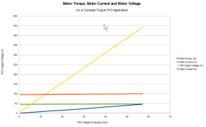
Voltage,Current, Torque and Speed on a Constant Torque VFD Application

What is a constant torque application?                                                                                                        Constant torque applications may have close to a uniform torque requirement across the motor speed range.  The bigger consideration from the perspective of drive selection is that these applications will require relatively high torque at low speeds compared to a pump or  fan.

The actual requirement arises from the load attached to the motor. For example a connveyor may need to exert significant torque at low speeds if there are objects already on it. Another example is a progressive cavity pump which relies on positive displacement to move fluid.

Why is it important to distinguish the requirements of constant torque applications     ( versus variable torque)?      

1. Higher torque at lower speed requires better speed regulation capabilities within the drive. Without speed feedback from the motor, drives rely on electrical feedback in the form of current and voltage as well as phase angle vector analysis between the two to regulate the speed loop. For example, if speed drops, the drive will have to increase voltage through its IGBT gating control on the output to effect a speed increase. This determination is made continously and rapidly and in both directions (  to increase or decrease output voltage) to maintain a speed setpoint.

2. Higher torque at lower speed requires for the drive to handle higher current draw at low speed.

If torque is the same throughout – what happens to voltage and current throughout the speed range?

This is where reverting to the motor torque formula is useful.

Torque formula

Observations based on this formula are:

1. If torque stays the same ( constant torque) and the VFD output frequency (and motor speed)  is increasing between 0-60Hz, horsepower or motor power consumption has to increase.

2. Motor power is going to be made up of two components of interest to us here ( assuming power factor and efficiency are constant) and they are voltage and current. Torque is proportional to current which infers that current will not change ( much). That leaves a variance in voltage, which also happens to be the component that the drive can alter with its voltage source inverter nature.

Some variance does occur in motor current. One possible reason is that motor impedance characteristics are affected by frequency- this is a topic of its own.

The graph at the top of this post shows the motor torque, motor voltage and motor current across the speed range. The load torque required in this example case is about 50%.


Share